

简单滤镜
在我们平时做图像处理的过程中,最长做的就是改变整体图像的某个颜色。
我们举个例子,如果做一个将所有 RGB 中的 R 值改为原来的 0.5 倍,根据上一个 wiki 里面所提到的,一张图表绘制的过程是先顶点 vertex 再 fragment,而 fragment 是负责绘制每个像素的颜色。
fragment float4 myFragmentShader(
                                VertexOut vertexIn [[stage_in]],
                            texture2d<float,access::sample>   inputImage   [[ texture(0) ]],
                                 sampler textureSampler [[sampler(0)]]
                             )
{
    float4 color = inputImage.sample(textureSampler, vertexIn.texCoords);
    return color;

}
所以就在这个 shader 里面将返回的 color 的 r 值乘上 0.5,就能够实现我们想要的效果。
return float4(color.r * 0.5 ,color.gba)
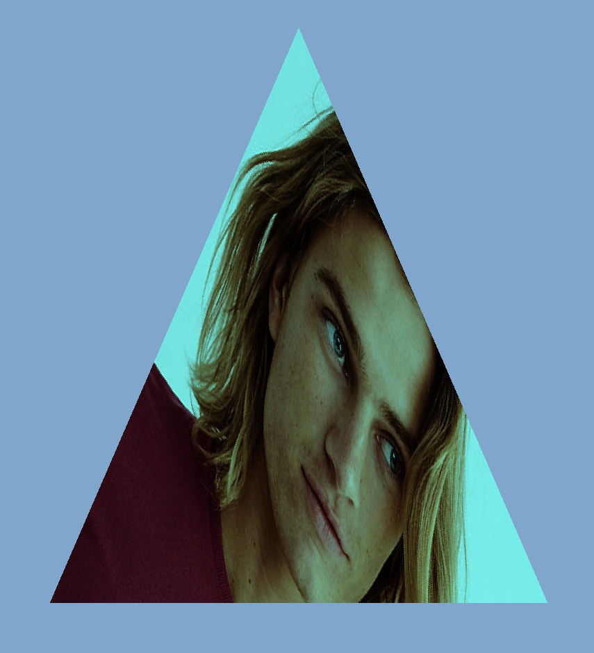
重新运行我们之前的 demo ,我们的三角就有点绿了,说明我们的效果实现了。
ColorLUT
但是上面是理想情况,一般图片的处理会复杂的多。
假设我们的图片是 1280 * 720 像素,那么就会进行 921600 的浮点运算,对每个像素的 r 值乘以 0.5。
如果图片小的话,对 GPU 的计算来说并没有什么压力,但是当图片更大并且数量更多的时候,就是会影响 GPU 计算的速度了。
look up table
顾名思义就是查找表,而 ColorLUT 就是颜色查找表。
所以引入了查询表,把对应的变换完的像素存起来,用的时候只要进行一次查询操作就可以,这样的操作会比之前的查表操作快的多,特别是在负载的颜色运算的情况下。
但是要把所有颜色的变换都存储起来,假设是 RGB24 ,一个是 8 3 24位,RGB 每个颜色都是 0-255,所有一共有 16777216 个颜色的变换,全存下来就是 256 256 256 24 / 8 / 1024/ 1024 = 48 mb,如果每个滤镜都是 48 mb 的话,那图片处理软件里面那么多滤镜,app 的大小不得没边了?
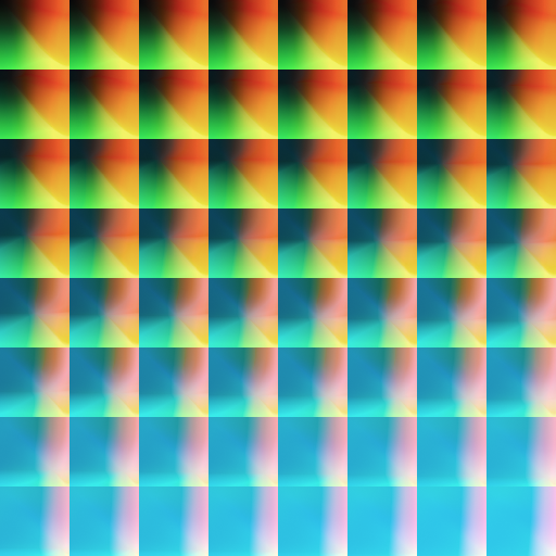
所以为了解决这一问题就有了 ColorLut 这样的标准滤镜图片,默认的是如下的图片,512*512 ,代表着所有颜色的变换,若不在图片中的颜色就去对应的差值:
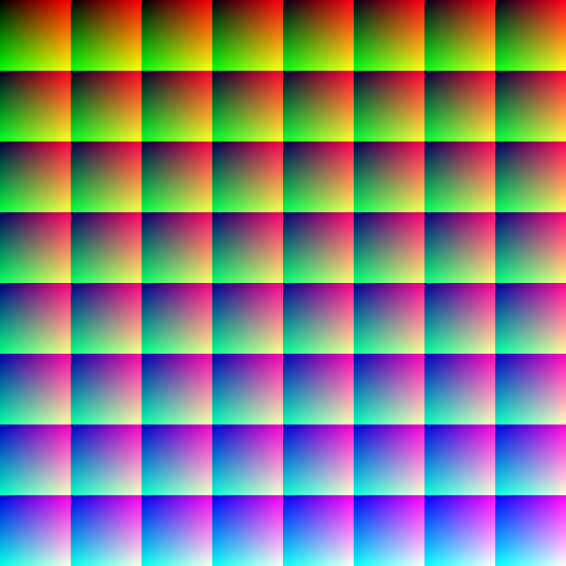
这是一张标准颜色的图,rbg 都是原来的颜色,所以对这张图片进行颜色的调整,然后得到一张新的 lut 图片,新的图片加上修改后的 lut 图片滤镜就可以查询到对应的颜色该怎么替换,从而的到新的图片。
下面我们来解释下上面的这张图片和如何使用:
首先观察一下这个图片
- 8*8 的方块组成
- 整体上看每个方块左上角从左上往右下由黑变蓝
- 单独每个个方块的右上角是红色为主
- 单独每个个方块的左下角是绿色为主
上述的信息有没有给你一点点启示呢?
我们在简化一点
颜色是 r g b 三个值,都以归一化的值表示( 1 代表 255 )。
- 整体对每个小方块而言,从左上往右下 b 从 0 到 1 ,是 z 字型的顺序
- 单独对每个小方块而言,从左到右 r 从 0 到 1,代表 x
- 单独对每个小方块而言,从上到下 g 从 0 到 1,代表 y
所以得到 0,0,1 的纯蓝色对应的位置就是 (7 64 , 7 64),右下角的那个方块。
现在让我们通过个例子,来演示一遍查询的过程。
假设我们现在需要获取的颜色是 (0.4,0.6,0.2) 都采用归一化坐标
- 首先我们确定用哪个方块 b = 0.2 * 63 = 12.6 即 (4,1)那个方块
- r = 0.4 63 = 25.6,g = 0.6 63 = 37.8 转换到大坐标(4 64 + 25.6, 164 + 37.8)
- 前三步得到的都是浮点数,但是我们滤镜的图像的像素都是固定的,不存在小数
- 对于 r,g 最后将的到的坐标再转换为归一化坐标,( (4 64 + 25.6)/512, (164 + 37.8)/512),通过取样器 sampler 插值取出精确颜色值
- 对于 b 我们可以通过对下一个方块 (5,1)再进行取色,再把两个颜色混合得到最后的颜色
Metal 图像处理
在上一篇中,我们提到 CommandBuffer 有三种 Encoder 。
- MTLRenderCommandEncoder 渲染 3D 编码器
- MTLComputeCommandEncoder 计算编码器
- MTLBlitCommandEncoder 位图复制编码器 拷贝 buffer texture 同时也能生成 mipmap
之前的 demo 是简单的对图像进行绘制,用的是 MTLRenderCommandEncoder 的 Encoder。
这次我们对图片添加滤镜,用到的是 MTLComputeCommandEncoder ,通过 GPU 的计算能力,来为我们实现查询 lut,并混合颜色的操作。
简而言之,相比之前的渲染操作,是输入图片的 texture 就能渲染出来了,滤镜我们需要做的是有个处理的方法,我们给 GPU 输入原始图片 texture 和 lut 图片的 texture , GPU 返回给我们一个新的添加完滤镜的图片 texture,我们把这个 texture 再给我们之前的渲染的 Encoder,就会在三角中绘制一张我们加过滤镜之后的图片了。
我们延续之前的 demo,Device 和 CommandQueue ,CommandBuff,默认都已经有了我们在之前的渲染的 Encoder 之前增加一个 Compute 的 Encoder。
每个 Encoder 都需要一个 PipelineState 负责链接 Shader 的方法
这里新建个 ComputePipelineState ,对应的 shader 方法稍后介绍。id<MTLLibrary> library = [device newDefaultLibrary]; id<MTLFunction> function = [library newFunctionWithName:@"image_filiter"]; self.computeState = [device newComputePipelineStateWithFunction:function error:nil];配置资源,原始图片和 lut 图片。
下面是 UIImage 转换为 Texture 的一种方法,通过 CGContext 绘制。
    - (void)setLutImage:(UIImage *)lutImage{
    _lutImage = lutImage;

    CGImageRef imageRef = [_lutImage CGImage];

    // Create a suitable bitmap context for extracting the bits of the image
    NSUInteger width = CGImageGetWidth(imageRef);
    NSUInteger height = CGImageGetHeight(imageRef);
    CGColorSpaceRef colorSpace = CGColorSpaceCreateDeviceRGB();
    uint8_t *rawData = (uint8_t *)calloc(height * width * 4, sizeof(uint8_t));
    NSUInteger bytesPerPixel = 4;
    NSUInteger bytesPerRow = bytesPerPixel * width;
    NSUInteger bitsPerComponent = 8;
    CGContextRef bitmapContext = CGBitmapContextCreate(rawData, width, height,
                                                       bitsPerComponent, bytesPerRow, colorSpace,
                                                       kCGImageAlphaPremultipliedLast | kCGBitmapByteOrder32Big);
    CGColorSpaceRelease(colorSpace);


    CGContextDrawImage(bitmapContext, CGRectMake(0, 0, width, height), imageRef);
    CGContextRelease(bitmapContext);

    MTLRegion region = MTLRegionMake2D(0, 0, width, height);
    [self.lutTexture replaceRegion:region mipmapLevel:0 withBytes:rawData bytesPerRow:bytesPerRow];

    free(rawData);
}- 配置可配参数,如滤镜的混合度,返回等等。
这里我新建了一个 struct ,代表了添加滤镜的返回和强度。通过 bytes 可以把相应的配置传到 shader 中去。
typedef struct
{

    UInt32 clipOriginX;
    UInt32 clipOriginY;
    UInt32 clipSizeX;
    UInt32 clipSizeY;
    Float32 saturation;
    bool changeColor;
    bool changeCoord;

    }ImageSaturationParameters;
配置 Encoder
将上述的组件都组装起来,sourceTexture 为输入的图片 texture ,destinationTexture 为将要写入的图片 texture,
self.lutTexture 为输入的滤镜图片 texture,分为对应为 texture 的 0,1,2 输入源。
把参数配置,作为 bytes 传入 shader 中。
ImageSaturationParameters params;
params.clipOriginX = floor(self.filiterRect.origin.x);
params.clipOriginY = floor(self.filiterRect.origin.y);
params.clipSizeX = floor(self.filiterRect.size.width);
params.clipSizeY = floor(self.filiterRect.size.height);
params.saturation = self.saturation;
params.changeColor = self.needColorTrans;
params.changeCoord = self.needCoordTrans;
id<MTLComputeCommandEncoder> encoder = [commandBuffer computeCommandEncoder];
[encoder pushDebugGroup:@"filter"];
[encoder setLabel:@"filiter encoder"];
[encoder setComputePipelineState:self.computeState];
[encoder setTexture:sourceTexture atIndex:0];
[encoder setTexture:destinationTexture atIndex:1];
if (self.lutTexture == nil) {
NSLog(@"lut == nil");
[encoder setTexture:sourceTexture atIndex:2];
}else{
[encoder setTexture:self.lutTexture atIndex:2];
}
[encoder setSamplerState:self.samplerState atIndex:0];
[encoder setBytes:¶ms length:sizeof(params) atIndex:0];threadgroups
在 Compute encoder 中,为了提高计算的效率,每个图片都会分为一个小的单元送到 GPU 进行并行处理,分多少组和每个组的单元大小都是由 Encder 来配置的。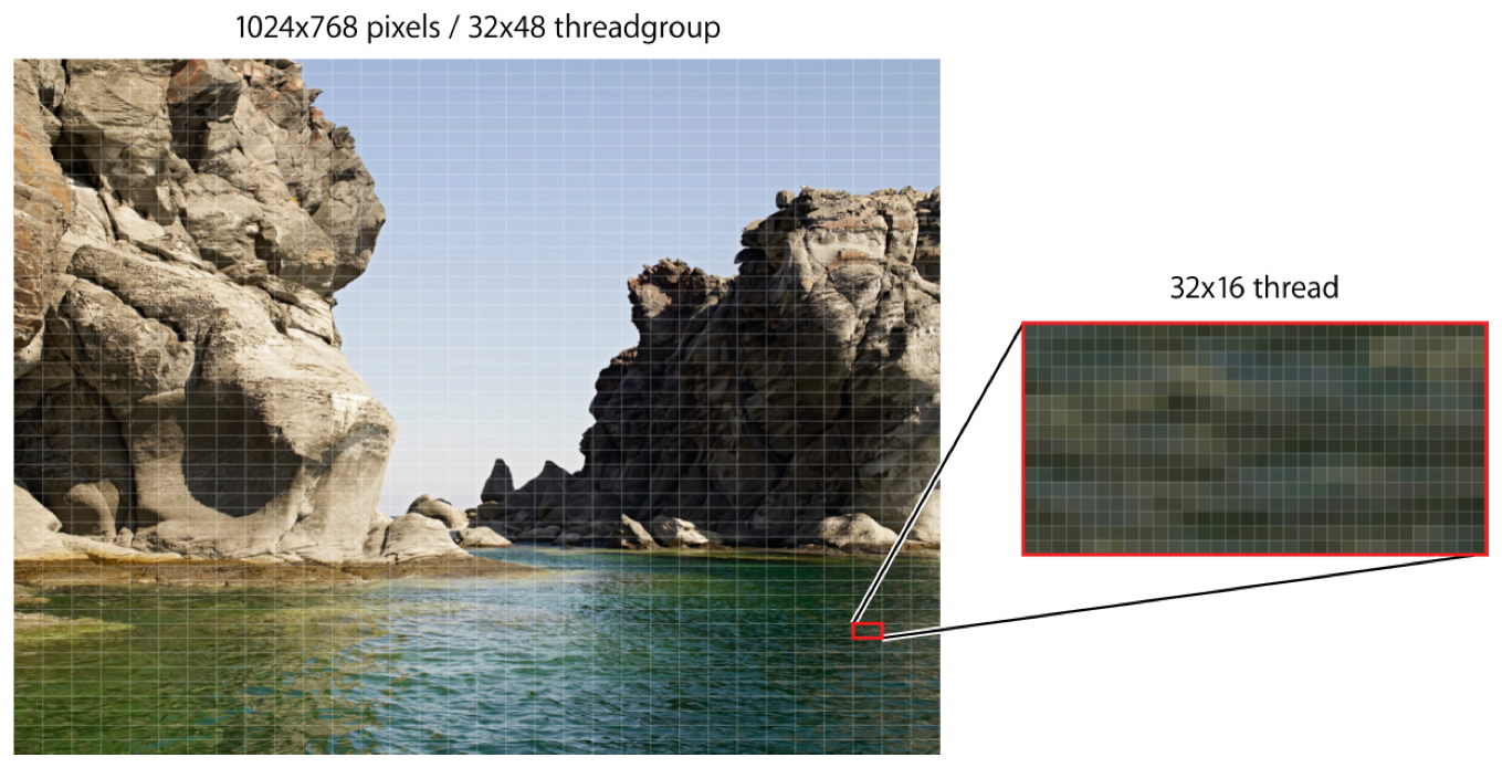
为了尽可能地发挥 GPU 计算最大的效率,可以通过如下方式来配置:
    NSUInteger wid = self.computeState.threadExecutionWidth;
    NSUInteger hei = self.computeState.maxTotalThreadsPerThreadgroup / wid;

    MTLSize threadsPerGrid = {(sourceTexture.width + wid - 1) / wid,(sourceTexture.height + hei - 1) / hei,1};
    MTLSize threadsPerGroup = {wid, hei, 1};


    [encoder dispatchThreadgroups:threadsPerGrid
threadsPerThreadgroup:threadsPerGroup];- Shader
这里也就是核心的计算逻辑,和之前渲染不同的是,它既不是 vertex ,也不是 fragment,而是新的 kernel 修饰的,具体的如下,其实就是上面的解释 lut 的代码版本,如果你能理解上面的 lut 坐标的定位的,那么下面的相关代码也不存在问题。
同时下面代码还增加了一个是否是需要添加滤镜的范围的判断,可以看到取样器是可以复用的,不同 texture 都可以使用同一个取样器。
可以看到 image_filiter 函数有 6 个输入值,从上网上分别为配置参数,原图 texture,写入的目标 texture,滤镜的 texture,采样器,执行时的位置(这个参数返回的是在之前配置的 threadgroup 中计算出来的,位于整个图像中的位置,不是归一化的值,直接取样即可获取对应位置的颜色)
//check the point in pos
bool checkPointInRect(uint2 point,uint2 origin, uint2 rect){
    return point.x >= origin.x &&
    point.y >= origin.y &&
    point.x <= (origin.x + rect.x) &&
    point.y <= (origin.y + rect.y);
}
kernel void image_filiter(constant ImageSaturationParams *params [[buffer(0)]],
                          texture2d<half, access::sample> sourceTexture [[texture(0)]],
                          texture2d<half, access::write> targetTexture [[texture(1)]],
                          texture2d<half, access::sample> lutTexture [[texture(2)]],
                          sampler samp [[sampler(0)]],
                          uint2 gridPos [[thread_position_in_grid]]){


    float2 sourceCoord = float2(gridPos);
    half4 color = sourceTexture.sample(samp,sourceCoord);


    float blueColor = color.b * 63.0;

    int2 quad1;
    quad1.y = floor(floor(blueColor) / 8.0);
    quad1.x = floor(blueColor) - (quad1.y * 8.0);

    int2 quad2;

    quad2.y = floor(ceil(blueColor) / 8.0);
    quad2.x = ceil(blueColor) - (quad2.y * 8.0);

    half2 texPos1;
    texPos1.x = (quad1.x * 0.125) + 0.5/512.0 + ((0.125 - 1.0/512.0) * color.r);
    texPos1.y = (quad1.y * 0.125) + 0.5/512.0 + ((0.125 - 1.0/512.0) * color.g);

    half2 texPos2;
    texPos2.x = (quad2.x * 0.125) + 0.5/512.0 + ((0.125 - 1.0/512.0) * color.r);
    texPos2.y = (quad2.y * 0.125) + 0.5/512.0 + ((0.125 - 1.0/512.0) * color.g);


    half4 newColor1 = lutTexture.sample(samp,float2(texPos1.x * 512 ,texPos2.y * 512));
    half4 newColor2 = lutTexture.sample(samp,float2(texPos2.x * 512,texPos2.y * 512 ));

    half4 newColor = mix(newColor1, newColor2, half(fract(blueColor)));


    half4 finalColor = mix(color, half4(newColor.rgb, color.w), half(params->saturation));


    uint2 destCoords = gridPos + params->clipOrigin;


    uint2 transformCoords = destCoords;

    //transform coords for y
    if (params->changeCoord){
        transformCoords = uint2(destCoords.x, sourceTexture.get_height() - destCoords.y);
    }
    //transform color for r&b
    half4 realColor = finalColor;
    if (params->changeColor){
        realColor = half4(finalColor.bgra);
    }

    if(checkPointInRect(transformCoords,params->clipOrigin,params->clipSize))
    {
        targetTexture.write(realColor, transformCoords);

    }else{

        targetTexture.write(color,transformCoords);
    }
}
7.计算
在上述步骤都配置完成之后,就可以 encode 了。
[encoder endEncoding];在执行上述步骤之后,我们就得到了一个添加完滤镜之后的 destinationTexture,将该 texture 传给之前的渲染流程,我们就可以获得一个带滤镜效果的三角形了!

对比下原图

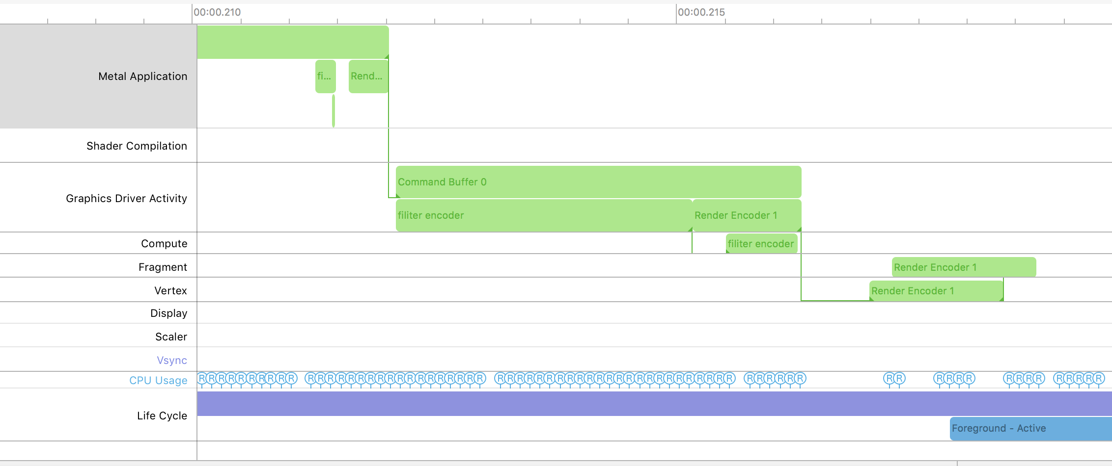
通过 Metal System Trace 根据 label 可以明显的看到,在我们的 render 之前多了一个 Compute 的 encoder。
#总结
上面是利用 ComputeEncoder 来实现的图像处理工作,其实通过 ComputeEncoder 能将一些复杂的数学计算转移到 GPU 上执行,如机器学习需要的大量的矩阵运算等。
总体的流程还是和之前的 Render 相同,唯一不同的可能是多了 threadgroup 的配置,
##参考:
wiki - Colour_look-up_table
Metal Programming Guide
使用CIColorCube快速製作濾鏡
